

Remote Battery Level Monitoring - System Integration and PCB design
GIT Repository : viewPosted on : 12 Oct 2024
Tag(s) : PIC16F1459, PCB, Remote-Monitoring, ESP8266
This is the final article in our remote battery monitoring series. In this article, we evaluate the system as a whole, combining all subsystems together. Additionally, we design the PCB (printed circuit board) for the system and cover various aspects of the project that have not yet been discussed.
System Overview
Before diving into the technical details, let’s start by visualizing the overall system. Below is the hardware diagram that outlines all the important components of our system.
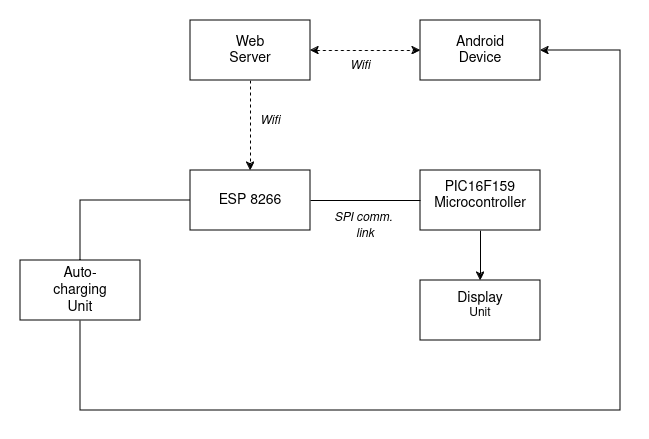
Most of the blocks in the diagram have been covered in detail in previous articles. If you missed any, be sure to check the related articles section at the bottom of this page. In this article, we will focus primarily on the auto-charging unit and provide a comprehensive evaluation of the system. Schematic diagrams, complete software code, and PCB designs will be included.
Auto-Charging Unit
The schematic diagram of the auto-charging unit is shown below.

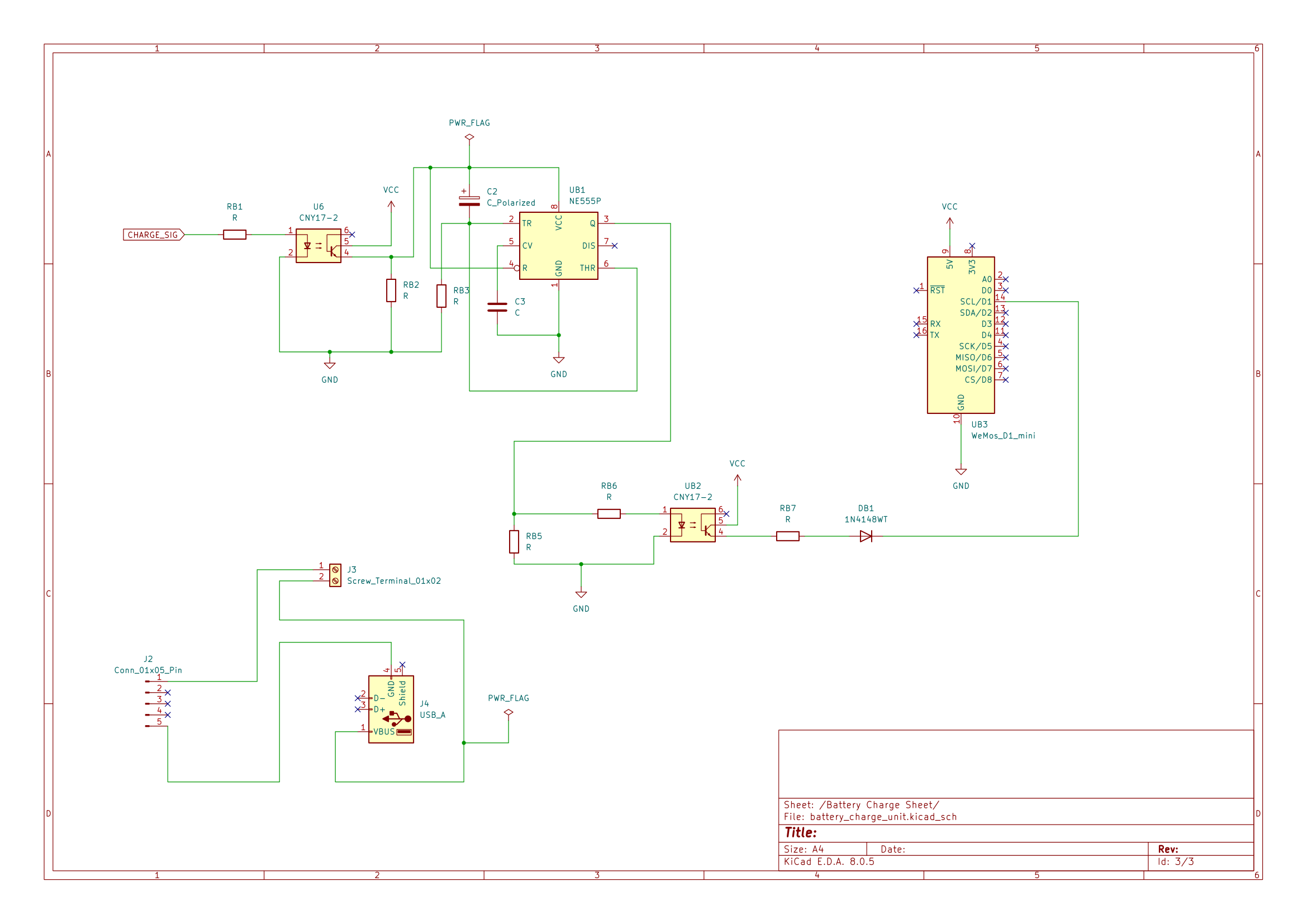
The control signal, labeled "CHARGE_SIG" in the diagram, is generated by the ESP8266 microcontroller. When the device needs to be charged or discharged, the ESP8266 toggles one of its GPIO pins from Low to High. This control signal is passed through an optocoupler and enters the NE555 timer circuit, which is operating in monostable mode as a delay-before-turn-on unit. This delay, set to 5 seconds, is crucial to prevent false charging due to transient voltages or erroneous signals from the MCU or other parts of the circuit.
During boot, for example, the NodeMCU board may pulse its GPIO pins, which could cause unwanted behavior. The delay-before-turn-on circuit prevents this by ensuring the system only activates after the defined delay period. For a detailed explanation of NodeMCU’s GPIO behavior during boot, check out Stephen Warren’s article here.
The delay, t, for the NE555 circuit is determined by the RC time constant and can be calculated using the formula:
t = 1.1 × C × R
The circuit was simulated using LTSpice, and the results are shown below:

In the simulation, the first trace represents the input 3.3V voltage, applied at t = 1s and removed at t = 17s. The second trace shows the delayed response from the NE555 timer circuit, which activates after 5.5 seconds. This slight difference from the calculated 5-second delay is expected, as the formula provides an approximation. For our system, a 5.5-second delay is acceptable, but if needed, reducing the resistor value can adjust the timing.
Once the delay period passes, the charging circuit is activated by energizing a 5V relay-shield module.
Microcontroller and Display Unit
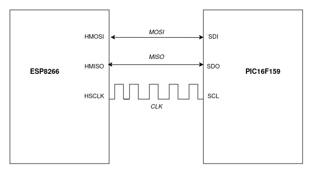
The PIC16F159 microcontroller receives the battery level data from the ESP8266 via an SPI communication link, as illustrated below.
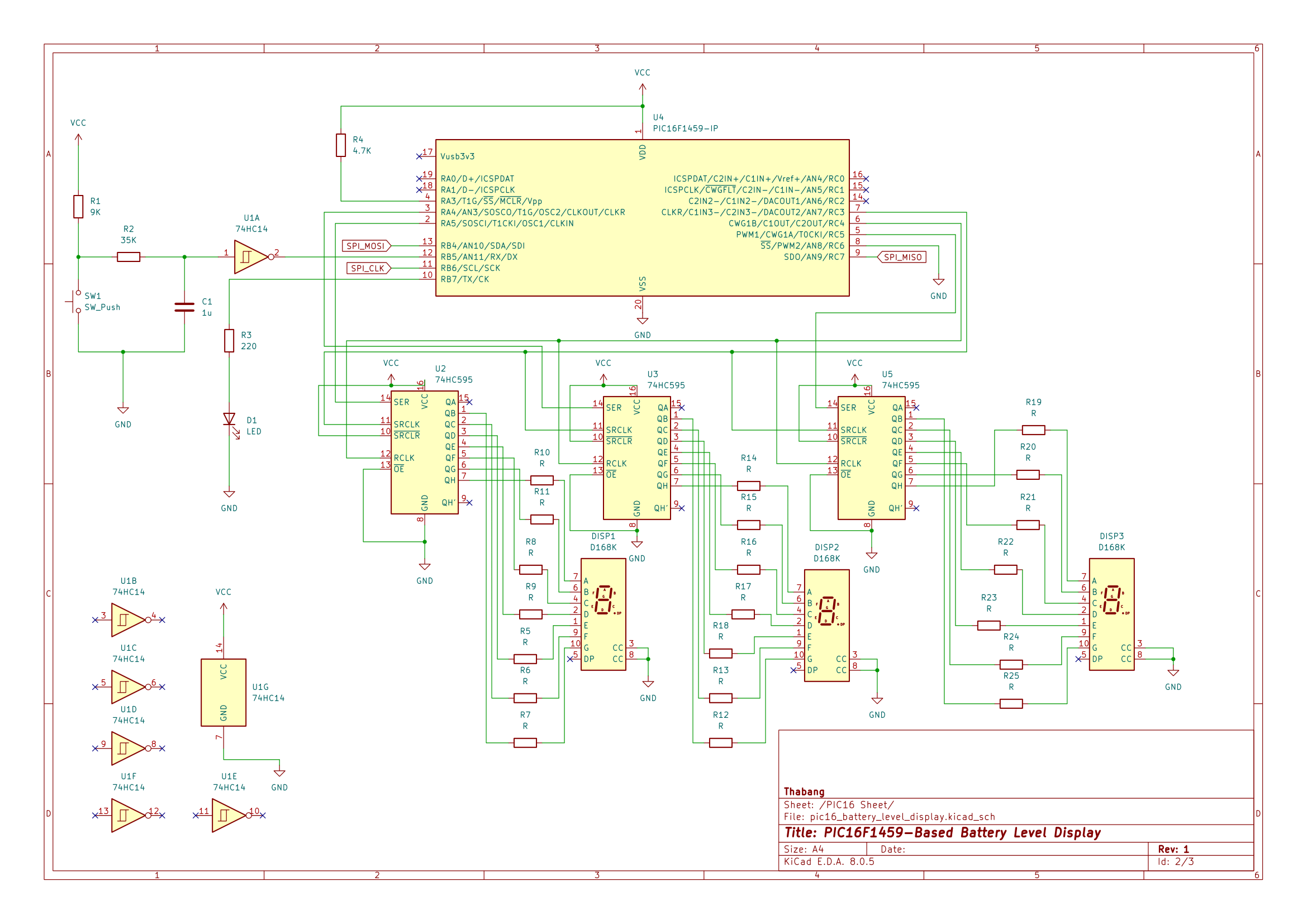
When the user presses a button, the PIC16 microcontroller displays the battery level on the 7-segment display by shifting the output bits to a shift register.
Software Code
The complete software code for the system is available on my personal Github here.
The PIC16F1459 code was developed using the MPLABX IDE and XC8 compiler. The NodeMCU was programmed using the Arduino framework on PlatformIO. Charging initiates when the battery level of the remote device drops below 8%, though this threshold is configurable. Additionally, if the internet connection to the web server is lost during charging, the system will attempt to reconnect three times. If unsuccessful, charging will stop to prevent further issues.
Circuit Diagrams
The complete circuit diagrams for the system are shown below:

PCB Design
The schematic capture and PCB design were done using KiCad version 8.0. Below is the complete board layout with routes, ground-fill, and annotations.

A print-friendly version of the layout, showing the routes without the back layer, is provided below:

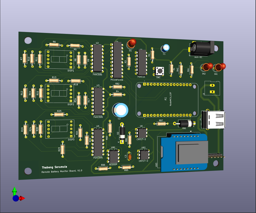
The 3D layout of the PCB board is shown below:
The system is powered by a 5V DC jack, which can be purchased off-the-shelf or designed as part of a separate power supply module.
Conclusion
This marks the final step in the development of our remote battery monitoring system. The entire system has been tested and evaluated, with a complete PCB design ready for manufacturing. From monitoring battery levels to automatic charging, this system showcases how hardware and software can come together to create an efficient solution. I hope this series has been informative and helpful in your own projects.
The last step is to send the PCB board for manufacturing and assemble the final product.
Other article related to this project
- Part 3: Remote Battery Level Monitoring - SPI Communications : Part 3
- Part 2: Remote Battery Monitoring - PIC16-based Display Subsystem : Part 2
- ESP8266-Based Remote Battery Monitoring and Low-Level Indication : Part 1
- SMSHub Connect : SMSHub Connect Android App