


Part 3: Remote Battery Level Monitoring - SPI Communications
GIT Repository : viewPosted on : 29 Sep 2024
Tag(s) : PIC16F1459, SPI, Remote-Monitoring, ESP8266
In this article, we continue building our remote battery monitoring system by adding a crucial component: SPI communication between the ESP8266 WiFi Module and the PIC16 microcontroller. In this setup, the ESP8266 will serve as the master controller, sending the battery level it retrieves via WiFi to the PIC16 microcontroller, which will act as the slave device.
System Overview
Before diving into the technical details, let's take a moment to visualize the overall system. Below is the hardware diagram, which outlines all the important blocks in our system:
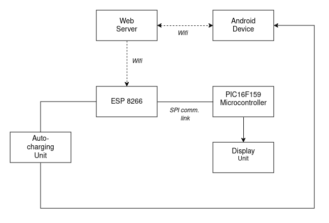
This article focuses specifically on the communication between the ESP8266 and the PIC16 microcontroller. For more information on the other subsystems, be sure to check out the related articles linked at the end of this post.
SPI Basics
Let’s start with a brief overview of SPI (Serial Peripheral Interface). SPI is one of several communication protocols used to transfer data between devices. In an SPI system, the master device initiates communication, while the slave devices respond only when spoken to by the master. One of SPI's advantages is its full-duplex capability, meaning that data can be sent and received simultaneously.
SPI uses four main lines for communication:
- MOSI - Master Out, Slave In
- MISO - Master In, Slave Out
- SCLK - Serial Clock
- SS - Slave Select
Each of these lines has a specific role in data transmission, and their names make their functions self-explanatory.
Circuit Diagram
Below is the schematic diagram showing the connections of our system on the PIC microcontroller :

The SPI pin connections between the ESP8266 and the PIC16F159 microcontroller are as follows:
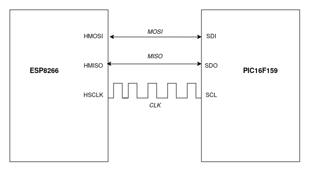
At this stage, we are not using the Slave Select (SS) line, as we only have two devices communicating with each other.
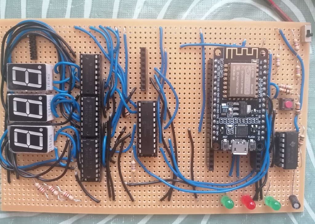
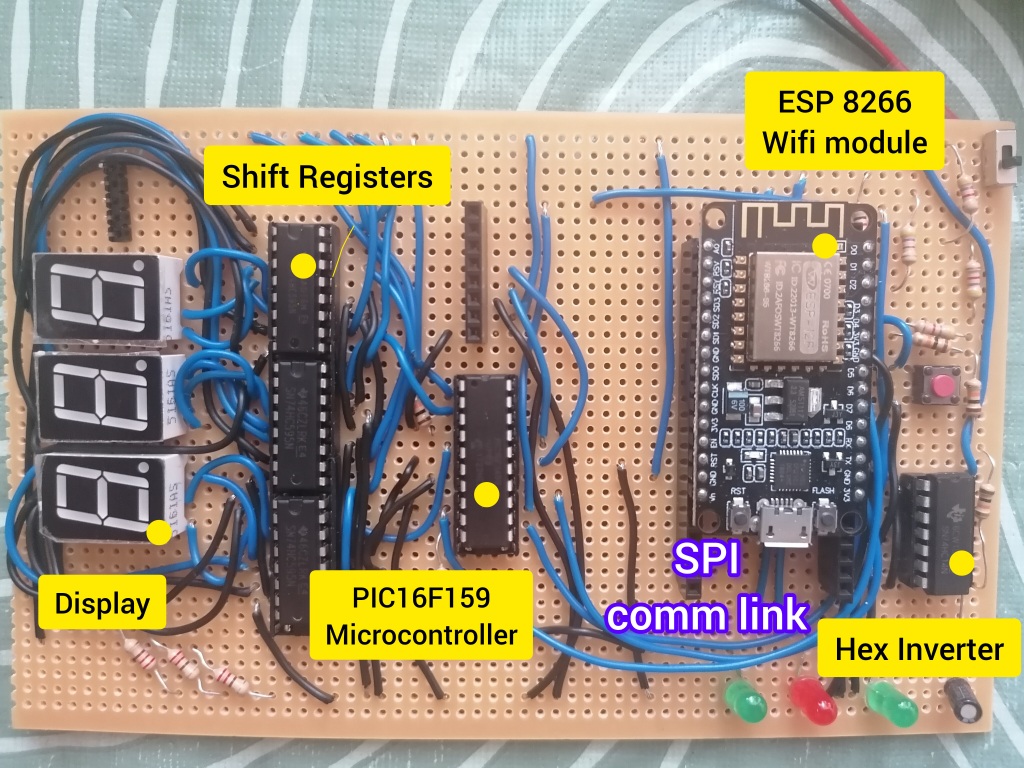
The circuit board, with the different components highlighted, is shown below:
Configuring SPI on the PIC16 Microcontroller
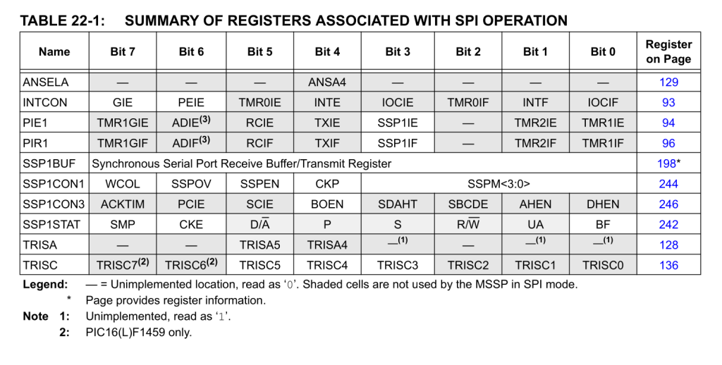
SPI on the PIC16 microcontroller is controlled by the Master Synchronous Serial Port (MSSP) module. To set up SPI, we need to configure three main registers:
- SSPSTAT - Status register
- SSPCON1 - Main control register
- SSPCON3 - Control register for some advanced features of SPI.
In addition to configuring these registers, it is necessary to set the appropriate pins for input/output using the TRISx registers. Additionally, we need to enable SPI interrupts through the PIE1 register.
SPI Clock Modes
SPI supports four different clock modes, depending on the configuration of the clock polarity (CKP) and clock edge select (CKE) bits. Selecting the correct clock mode is crucial to ensure that data is sampled correctly.
In our setup, we are using CKP = 0, CKE = 1.
The code snippet below shows how we configure the MSSP module for slave mode on the PIC16F159:
void setSPIMode() {
    // Set SPI Pins (B6, B4, C7, C6)

    TRISBbits.TRISB6 = 1; // CLK
    TRISBbits.TRISB4 = 1; // SDI
    TRISCbits.TRISC7 = 0; // SDO
    TRISCbits.TRISC6 = 1; // SS

    // Configure SSP1CON1<5:0>
    SSP1CON1 = 0b00100101;

    // (7) WCOL = 0 [No collision]
    // (6) SSPOV = 0 [No overflow] -> Data must be read from buffer
    // (5) SSPEN = 1 [Enable SPI serial port]
    // (4) CKP = 0 [Clock Polarity] -> Idle state is Low
    // SSPM<3:0> = 0101 [SPI Slave mode] -> clock = SCK pin, SS pin control disabled

    SSP1STATbits.BF = 0;
    SSP1STATbits.CKE = 1; // Transmit occurs on transition from active to idle clock state
    SSP1CON3bits.BOEN = 0; // [Buffer overwrite disabled], -> If New data is received while buffer is full, the SSPOV bit of the SSP1CON register is set

    PIE1bits.SSP1IE = 1; // MSSP Interrupts enabled
    PIR1bits.SSP1IF = 0; // Clear interrupt flag
}
Configuring SPI on the ESP8266
For the ESP8266, we use the Arduino framework to simplify the code and reduce development time. Fortunately, the ESP8266 comes with an SPI library, which makes adding SPI into our project straightforward. We will use PlatformIO IDE to include and use this library in our project.
Data Transmission Payload
The ESP8266 will continuously transmit the battery level data to the PIC16 microcontroller via the SPI interface. The data payload format is as follows:

In this format, the characters ‘A’ and ‘Z’ mark the start and end of each transmission, so that the PIC16 knows when a full data packet has been sent.
Data Reception on the PIC Microcontroller
The PIC16 receives data from the SPI bus and stores it in the SSPBUF buffer. Once the buffer is full, an interrupt is triggered, allowing the microcontroller to read the data. Below is the code for our interrupt service routine (ISR) that handles data reception:
// Our Interrupt Service Routine
void __interrupt() ISR(void) {
    if ( PIR1bits.SSP1IF ) { // SPI data reception

        // Clear the interrupt flag
        PIR1bits.SSP1IF = 0;

        if( SSP1CON1bits.SSP1OV == 1 ){
            // There is a data overflow error. Discard the received byte
            SPI_Read();
            SSP1CON1bits.SSP1OV = 0; // clear overflow flag
        }else{
            // Read the received data from SPI Buffer
            received_data = SSPBUF;

            // check input data state
            if( received_data == 'A'){
                // start of transmit sequence
                spi_index_count = 0;
            }

            if( spi_index_count < 5 ){
                spi_tmp_buffer[spi_index_count] = received_data;
                spi_index_count++;
            }

            if( spi_index_count >= 5 ){
                if( received_data == 'Z'){
                    // End of transmit sequence

                    // Copy contents into our main buffer
                    size_t len = sizeof(spi_tmp_buffer)/sizeof(spi_tmp_buffer[0]);

                    for( int x = 0; x < len; x++){
                        spi_input_buffer[x] = spi_tmp_buffer[x];
                    }

                }
            }
        }
    }
}
Complete Code
The complete code for this project is available on my GitHub here.
Video Demo
Conclusion
In this article, we successfully established SPI communication between the ESP8266 and the PIC16 microcontroller. With this communication link in place, the ESP8266 can now transmit real-time battery data to the PIC16.
In the next part of the project, we will focus on building the automatic charging subsystem, ensuring that the monitored battery can be efficiently recharged when its level gets too low. Stay tuned!
Other article related to this project
- Part 2: Remote Battery Monitoring - PIC16-based Display Subsystem : Part 2
- ESP8266-Based Remote Battery Monitoring and Low-Level Indication : Part 1
- SMSHub Connect : SMSHub Connect Android App