


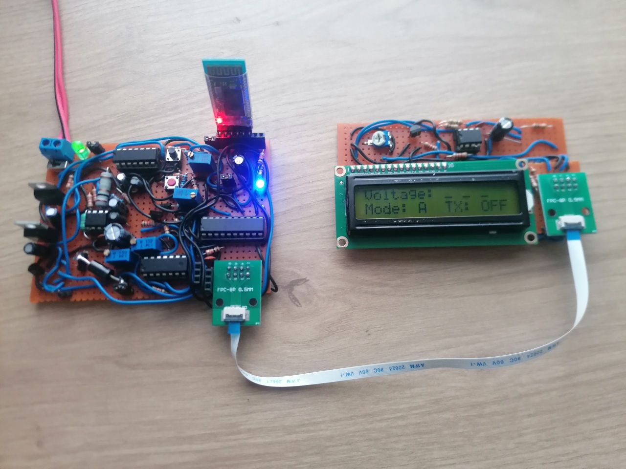
Updated Real-time Voltage Sampler with DC-DC Boost Converter and LCD Backlight Control
Posted on : 26 Dec 2025
Tag(s) : PIC18, 555 Timer, DC-DC Boost, Batteries
This project builds on the previous real-time periodic voltage sampler. I updated the project to increase the input voltage range to 14V, and swapped out the 7-segment displays for a more convenient LCD display. I also removed the EEPROM functionality - instead, the device now transmits voltage samples in real time over a UART interface. This new approach simplifies the design and lets us send more data without worrying about storage limits.

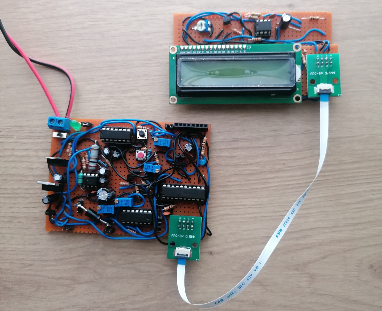

Motivation for this project
The main reason I built this periodic voltage sampler is to monitor battery voltages over time. So it's important that the circuit provides accurate measurements and a wide voltage range to handle different batteries. That's why I increased the input range up to 14V, so that I can easily monitor 3V, 6V, 9V, and 12V batteries.
System Requirements
- Measure voltages up to 14V
- Voltage accuracy within 0.5% of a multimeter
- Transmit voltage samples via UART
- Overvoltage protection for inputs above 14V
System Overview
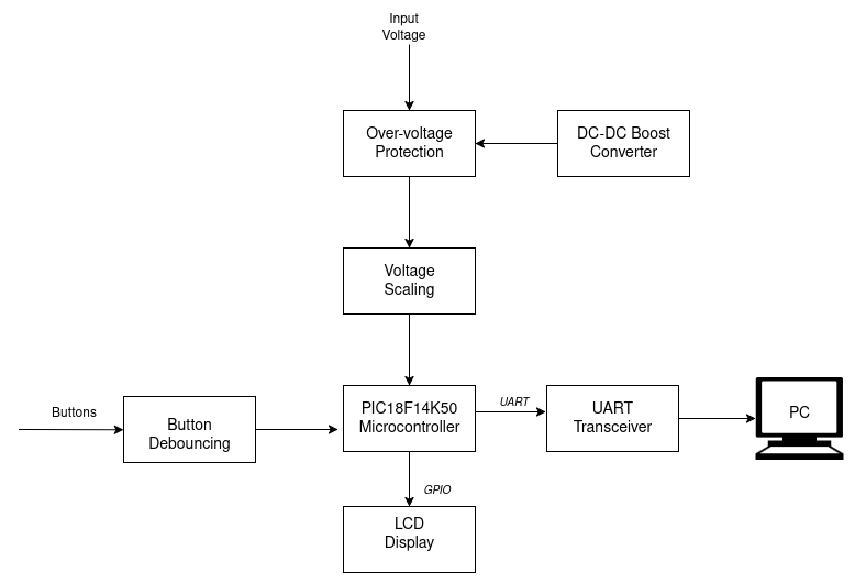
The hardware block diagram for the system is shown below:
Over-voltage protection:
The input voltage goes through an overvoltage protection subsystem to keep it within the 0–14V range. This is done with a voltage comparator circuit, powered by an 18V supply from a DC-DC boost converter. If the input voltage exceeds 14V, the NMOS transistor switches on and clamps the excess voltage to ground.
Microcontroller:
I used the PIC18F14K50, an 8-bit 20-pin MCU, programmed in C with the MPLAB XC8 compiler. It controls the LCD display using 6 GPIO pins. The MCU's ADC handles voltage sampling with an external 3.3V reference.
LCD Display:
The system uses a 16x2 LCD based on the HD44780 chipset. The MCU drives it with 6 GPIO pins. The backlight is controlled in hardware with a 555 delay-on timer circuit, this was necessary because I ran out of GPIO pins on the PIC18 :-D .
Buttons:
Two push buttons are used for mode selection, debounced both in hardware and software.
UART Interface:
An HC-05 Bluetooth module transmits the UART data to a PC or mobile device.
Hardware Details
Design of the DC-DC Boost Converter
The design requirements for the DC-DC boost converter are as follows:
- Input Voltage (min): 12V
- Output Vout (nominal): 18V
- Maximum ripple: 0.5% of Vout = 90mV
- Minimum switching frequency: 10 kHz
Design Calculations
Here's the procedure I followed to design the DC-DC step-up converter using the MC34063 IC.


Design Simulation
The image below shows the schematic of the DC-DC boost converter and the corresponding transient response simulation from LTspice.
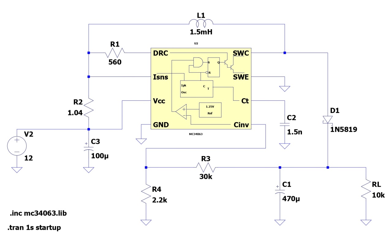

The nominal output voltage is around 18.34V, as shown below along with the voltage ripple.
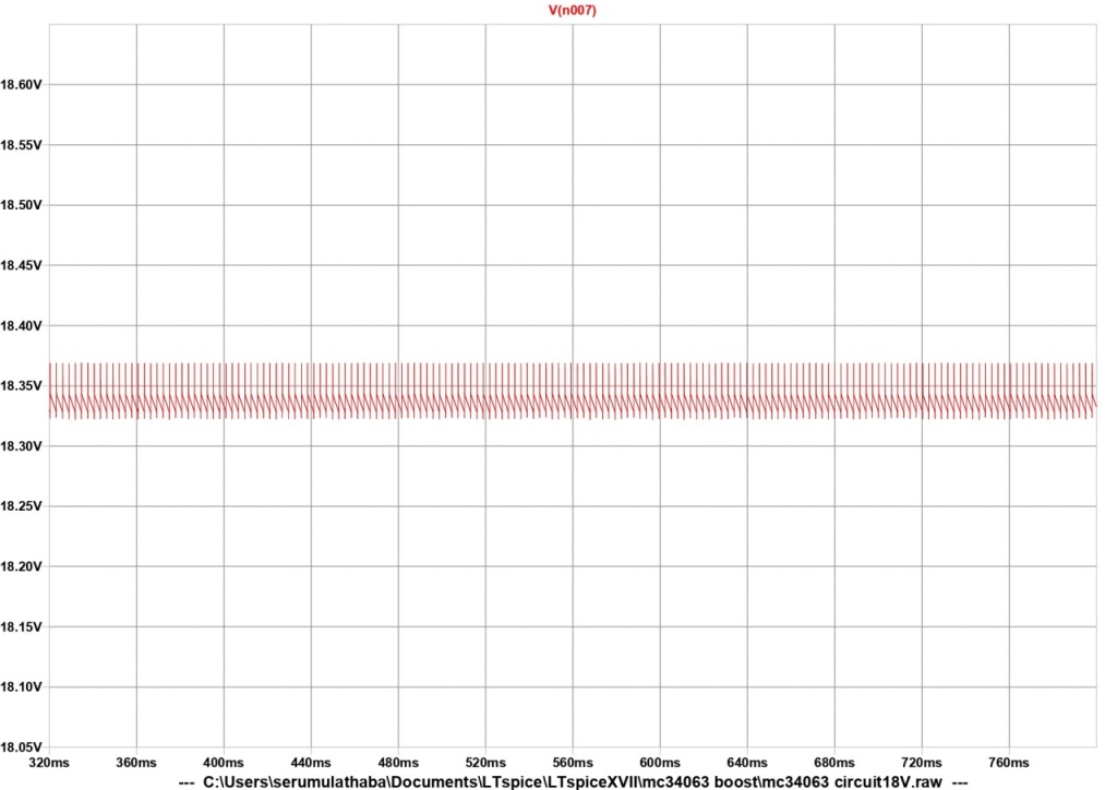

The simulation shows that the circuit meets the design specs. However, there's a large initial overshoot, and the output takes a while to stabilize (~300ms), mainly because of the slow switching rate. A design with a higher switching frequency would work better.
Overvoltage Protection and ADC Voltage Scaling
The input voltage is limited to the ADC's safe operating range by the circuit below:

This setup protects the ADC from overvoltage while keeping good accuracy for voltage sampling. It ensures the voltage at the ADC pin never exceeds 3.3V. The simulation results below show the "ADC_IN" voltage and the current through R7 as VIN is swept from 0V to 20V:

As you can see, when the input voltage exceeds 14V, the op-amp comparator triggers and the NMOS switch clamps the voltage. The ADC input never goes above 3.3V. If the op-amp comparator fails, the Schottky diode clamp takes over and limits the voltage below 3.3V.
Power Supplies
The circuit takes 12V input from a DC jack. That voltage feeds into three regulators: two 3.3V and one 5V. The second 3.3V regulator provides the external reference for the MCU's ADC. There's also the DC-DC boost converter that supplies 18V to the overvoltage protection circuit.
LCD Backlight Control using 555 Timer
The 16x2 LCD needs at least 7 GPIO pins for full control (E, RS, K, PB4, PB5, PB6, PB7). But I only had 6 pins available on the PIC18. To get around that, I used a hardware solution. The circuit below automatically turns on the LCD backlight when there's activity on any LCD pin. Here I used the LCD_Enable pin - when it goes low to high, the 555 timer turns on the backlight for a pre-set delay.
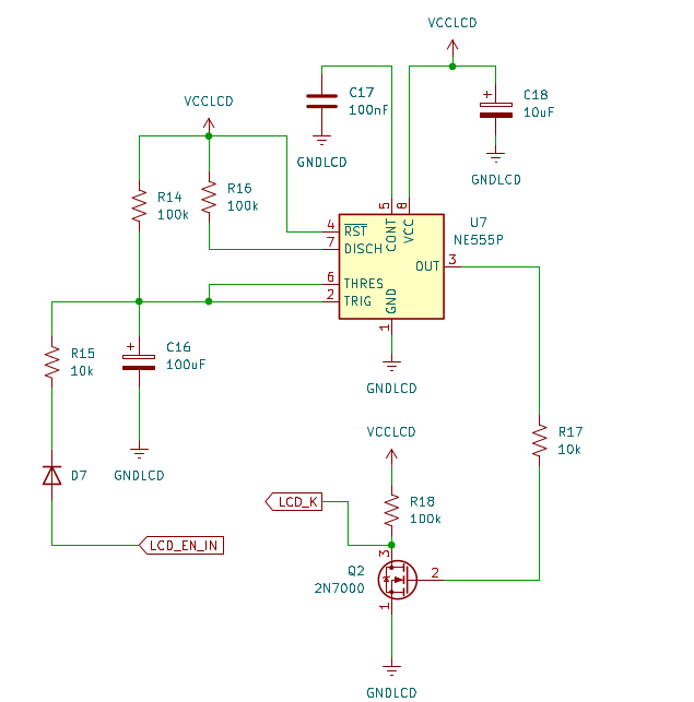
The delay time is roughly t = 1.1 × R × C.
System Operation Results
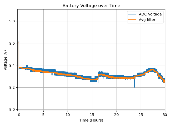
The image below shows a Lead-Acid battery charging profile measured with the device:
Things that work well
- LCD backlight control – The 555 timer circuit successfully turns on the backlight whenever the MCU writes characters to the screen.
- Firmware – The PIC18 firmware handles the state machine, UI, and UART transmission to the Bluetooth module without issues.
- DC-DC boost voltage – The boost converter outputs 18.2V from a 12V input, with or without a load.
- ADC sampling – The PIC18 delivers real-time voltage samples successfully.
Things that need improvement
- Regulated power supply – The 5V linear regulator dissipates too much heat (it's dropping 12V down to 5V) and needs a heatsink. To fix this, I could add an intermediate adjustable regulator set to around 8V before the 5V regulator, or use a buck-converter which is more energy efficient.
- DC-DC boost switching frequency – The switching frequency is low, falling into the audio range, which makes the large inductors and capacitors noisy. A higher switching frequency (>100 kHz) would be better.
- Overvoltage protection clamping resistor – The 10Ω resistor connected to the NMOS switch needs a higher power rating, since it conducts more current during an overvoltage fault.
- ADC Sampling Accuracy at Low Voltages – The ADC gets less accurate when measuring voltages below 2V. This could be caused by the high-impedance voltage divider at the input, since it limits the current flowing into the ADC's sample-and-hold capacitor, making it harder for the ADC to get a clean reading. The capacitor doesn't charge up fast enough or fully enough before the conversion starts.
System Schematic Diagram
 System Schematic - View / Download PDF
 Kicad (v9.0) Project Files
Conclusion
This project showed how to build a voltage sampler using a PIC18 MCU to monitor battery voltage and stream real-time sample data to a PC over Bluetooth. It also demonstrated how a 555 timer delay circuit can control an LCD backlight when you don't have enough GPIO pins. I also designed a DC-DC step-up converter to boost 12V to 18.2V. The design highlighted the need for a higher switching frequency - otherwise the inductor and capacitor can get noisy and fall into the audible range.
Firmware Code
The complete firmware code for project is available on my GitHub repository. The project code is for MPLAB X IDE with the XC8 compiler.
Further reading
- Part 1: Real-time Voltage Sampler using PIC18 and Persistent EEPROM Storage : Part 1