
Periodic Data Sampler using PIC18 and Bluetooth module
Date : October 20204-5 Min
Posted on : 15 May 2022
Tag(s) : Solar Project, PIC18
The goal of this project was quite simple, i had a solar charging circuit and i wanted to have near real-time data on the various voltage levels from the solar panels to the batteries i was charging. The picture on the left shows what the final design looks like and how i was using it. The solar charger was placed next to the window and the device is mounted on the wall where it continuosly sends data to the PC using bluetooth.
The micro-controller i used for this project is the PIC18F45K20 from Microchip which has about 13 analog-to-digital converter (ADC) channels available. The analog input channels can be used and connected to different nodes on the solar charging unit depending on what we want to measure. The bluetooth module used was the HC-05 which can communicate with the PIC18 device using the (USART) serial ports. The PIC18 was programmed using C-language with the MPLAB IDE. Furthermore, the PIC18 sampler is plugged in to the wall socket using a 5V USB phone charger adapter which acts as the power supply to the module. A low dropout voltage regulator is then used to reduce the voltage from 5V to 3.3V for the PIC18.
The blue cable in figure 1 is a standard LAN cable that was cut on both ends and connected with PIN headers so that the ADC channels of the PIC can be connected to the solar charger in a convenient manner and with less wiring. This is shown below :

The output of the voltage regulator is used as the power supply to the micro-controller but also as the reference voltage (Vref) to the ADC. For this reason, the voltage regulator needs to be the low dropout kind so that the voltage measurements are more precise. The ADC was configured in polling-mode so that the ADC channels are read in sequence one after another. The sampling is activated by a timer interrupt that is triggered every 2 minutes. In code, the microcontroller takes the voltage samples and converts the values to floating point numbers and stores them as a character array separating the values of each ADC channel by commas as shown below,
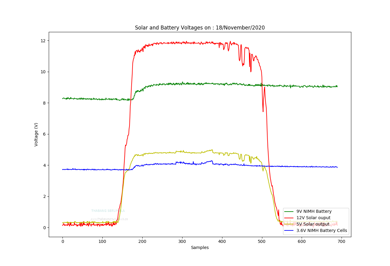
voltages: ADC0, ADC1, ADC2 , ADC3, ADC4,....This character array is then transmitted through the USART serial pins of the micro-controller to the bluetooth module which then relays the data to the PC via the air interface. The data from the microcontroller is processed using a Python script running on the PC which creates daily log files. The data from these log files can be used to create plots such as the one shown below
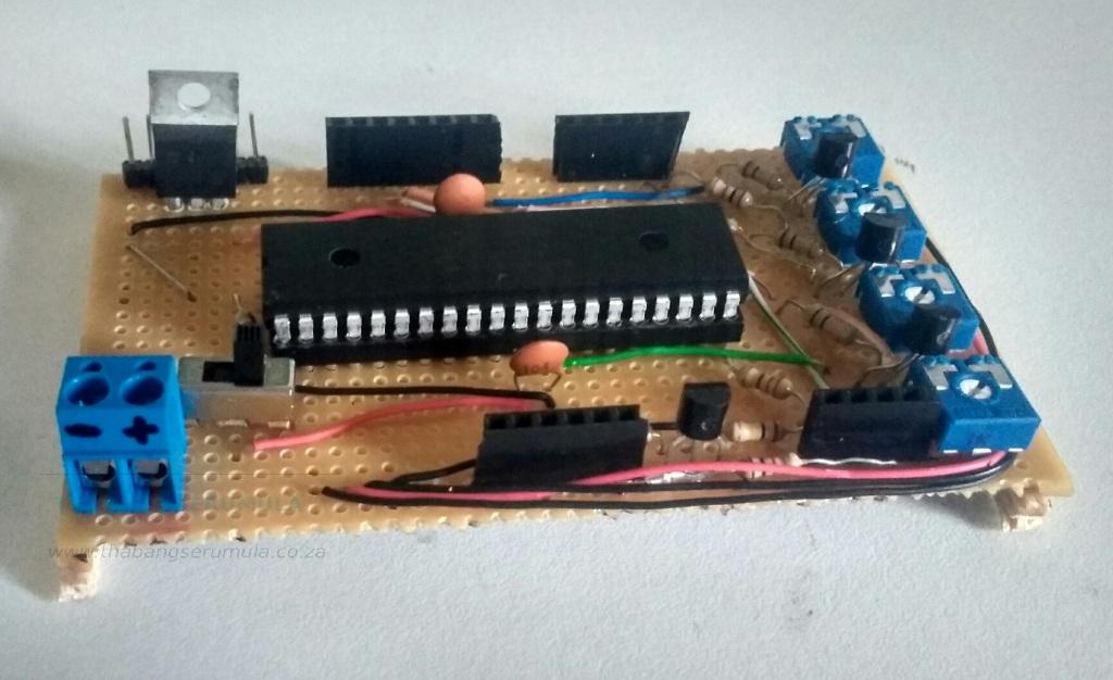
The circuit for this project was placed on a veroboard as shown in the picture below