

Optical free-space communication system using laser diodes.
Date : March - November 20219-12 Min
Posted on : 13 May 2022
There is a clear trend in telecommunications to obtain more bandwidth and to keep up with the rising demand from consumers. Wireless systems using radio and microwave wavelengths have long been used by network operators but they are limited by the spectrum they have available and the licensing costs to use such spectrums are very high. A good alternative to wireless systems is optical communication networks which are the main focus of this article.
The design of such a system was part of my final year engineering project and this article i will describe my personal experiences while working on this project and how well the system worked according to specifications aswell as how future work can expand on this to improve the system further. This article does not go through the full technical details of the design process but is only meant as a review of the system and to highlight the work that was done. The specifications of the system was for a data rate of 64kbps on each of the optical links(lasers), a bit-error rate of 1e-6, and for the lasers to automatically align with the photon-receivers within 60 seconds.
The first few months were mainly dedicated to doing research and consulting with the available literature on the subject. I was surprised to find that free-space optical communications was still in its infacy even though the technology has been available for more than a decade. Optical networks are mostly reserved for communications between buildings on the rooftops at short-to-medium distances( few kilometres) but can also be used in satellite communications over long distances. Infrared-light is commonly used for long-range communications while visible-light is appropriate for the shorter distances. Atmospheric effects must be considered while choosing the optical wavelengths. The light travelling might be absorbed or scattered in the atmosphere. For example, we will experience Rayleigh scattering when the size of the air molecules is a tenth smaller than the wavelength of the light wave. This is part of the reason why the sky looks blue because the short wavelengths of sunlight are scatterred. To help avoid this scattering effect, 850nm and 1550nm (Infrared) lasers are commonly used in FSO networks but they are also more expensive. I was using red (650nm), green(530nm), and blue(450nm) light for this project. There is an analysis of optical transmission windows using a LOWTRAN 7 model and the data shows that the red, green, and blue are pretty good for short distances and that the Rayleigh scattering are not much of an issue. However, There are also other Atmospheric effects to consider like the weather (rain, smog, fog, ...etc).
After the literature study, i went through a link margin calculation using parameters for a 100mW blue laser diode and meteorological data for clear air/ light-mist wheather conditions. The following graph shows how far the system can (theoretically) be expected to work.

The link margin needs to be above 3dB and the figure above indicates that the system will remain functional for a distance of about 1.5km. A greater distance can be reached by increasing the optical power of the lasers or by changing the divergence of the laser beam or increasing the surface area of the receiver.
The circuit designs also formed a large part in this project. The transmitter and receiver subsystems include a constant-current laser driver, transimpedance amplifier and an anti-aliasing filter. The signals are modulated and de-modulated using a digital-signal processor (DSP). The model used was the STM32-F429I. Moreover, I had to design motor driver circuits for bipolar and unipolar stepper motors. Some of these might appear simple on the surface but the performance requirements were strict and so i had to make sure that the final system will meet the specifications. For this reason a significant amount of time was spent on simulations. An example of some of the circuits is shown below


The functionality of the system was simulated in code using Python. I tested the method of using optical spreading codes which allow for the simultaneous transmission of data from/to multiple users. This is a bit similar to code-division multiple access (CDMA) using in 3G networks but the spreading codes were designed specifically for optical communications. These were provided to me from my mentor as the design of such codes was outside the scope of this project. Additionally, the signals were transmitted using Manchester-encoding as shown below.

While this worked great in simulation, the practical implementation using this encoding method was incomplete as it had bugs and some framing errors. I later had to replace this with a standard NRZ-encoding scheme. This was okay for demonstration purposes but the Manchester encoding was preferred for my design as it was more robust (even though it doubled the bandwidth requirement.)
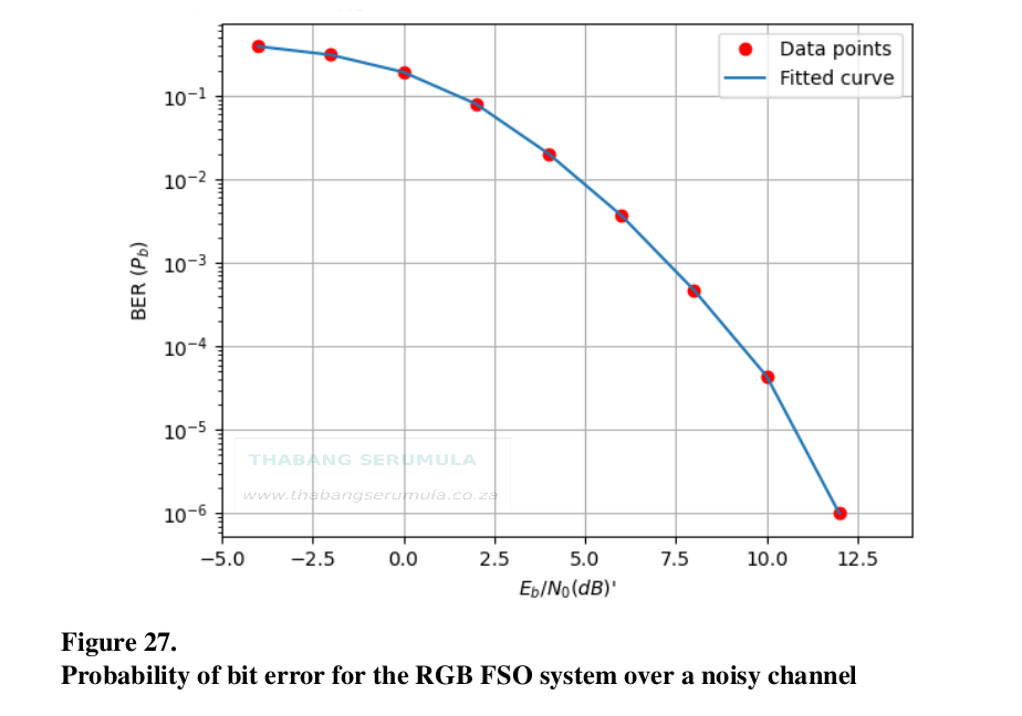
Moving on, the plot below shows the bit-error rate (BER) performance of the system from the Python simulation. Making this graph was quite a challenge because i could not run the simulation on my laptop. I had to process millions of data samples but my laptop doesn't have enough memory or processing power for this. It would always freeze during the simulation but luckily i found a computer on campus that could handle this task. The plot below show that an SNR of 12 or greater is needed to achieve a BER of 10-6.
Furthermore, I also designed a 1/2 convolutional encoder and decoder using the Virtebi-algorithm for error correction, although this was not added to the final physical implementation because of time constraints. Here is a screenshot from the Python console showing the decoded data bits and messages on the receiver.
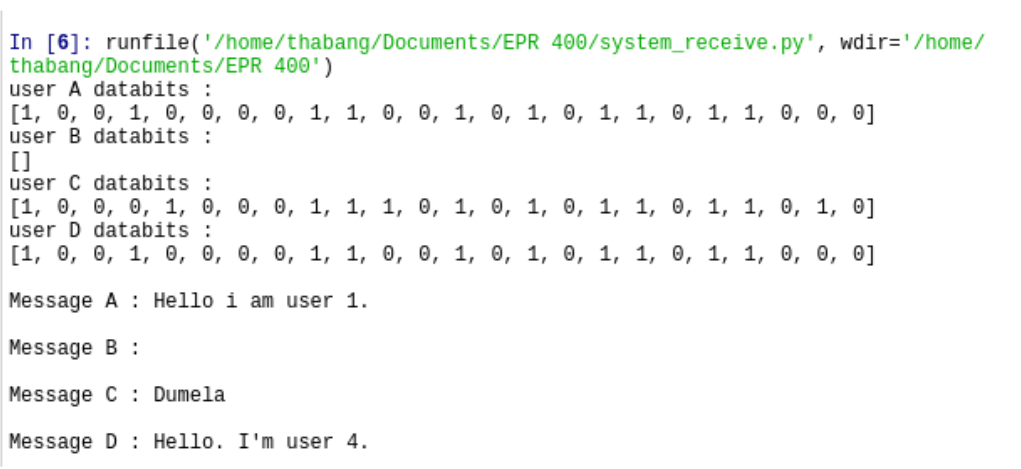
Overall the system worked very well from the Python simulations.
The auto-alignment was the hardest challenge in the design of this system. The task was to move the photo-diodes on the device and to align them with the incoming laser light from the transmitter. The communication system is full-duplex so this has to work in both directions. The picture below shows the model i created to solve this task. Here i am using the Free-CAD (open-source) software to design the mechanism.

It was my first time using the software and most of it was a steep learning curve. The parts had to be modelled and fitted together using the software. Here is an example of creating a pulley for the belt system:

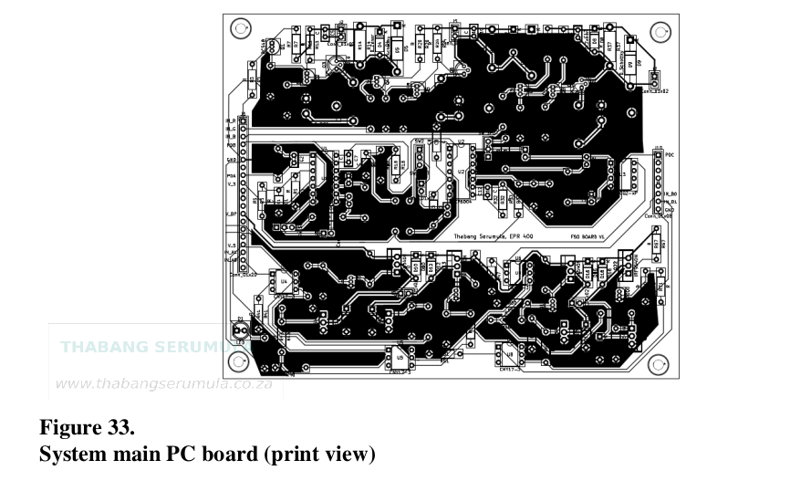
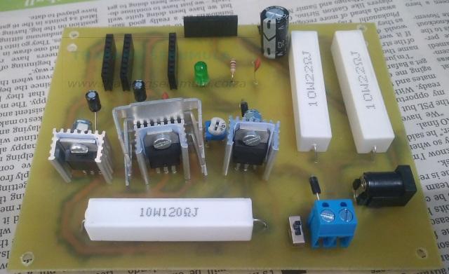
After all the circuits were designed and tested, the next step was to produce a printed circuit board (PCB). The PCB layouts were made using the Ki-CAD (open-source) software. They are two-sided PCBs and I had them printed in China by JLCPCB. It took only 2 weeks to receive the boards, which was quick given that i did not use an expensive shipping option. My budget was always tight for the entire duration of this project. I recall having to decide between buying food or getting soldering wire. College life am i right? (sigh), anyway, I'll save that story for a different time. The board with the main electronics is shown below

The layouts for other subsystems such as power supply, unipolar stepper motor driver, and the user-interface were printed on a single-layer board using ferric chloride (FeCl3 ) solution. The power supply and stepper motor driver are shown below.
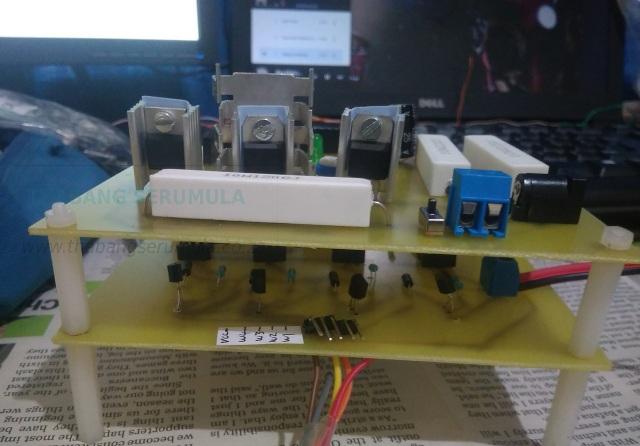
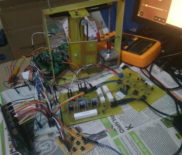
The remaining step was to do integration and assemble all the different subsystems. Since i did not have the financial resources to do 3D printing of the device, i had to come with a creative solution that will ensure the device functions as needed but remains small enough to fit in a shoe box. This solution was to construct various shapes from a PCB with the copper layer stripped off except at the edges. The device frame could then be fabricated by joining the parts and soldering the edges at 90 degree angles. The picture below shows the constructed device aswell as the PC boards for the different subsystems aswell as the DSP.
The final designed device is shown below. There are two of these in total and they are separated by a distance of 10 metres or more. The mechanism with the photo-diodes moves in a two-dimensional plane( up-down, left-right). Although, the best design option for the front plate is to use collimation on the photo-diodes such that the incoming light can be focused in a tube at a specific focal length to ensure the best performance. Nonetheless, the chosen design option was okay for short-range communications as the algorithm running on the DSP was robust enough and very precise at moving the plate to the correct location.

It is worth mentioning that there is a lot that goes on with the DSP that was not described in this article. The signal processing serves a large part of this project and a significant amount of time was dedicated to it. However, the details were omitted for brevity and to ensure that this article remains less technical. Perhaps i might write another piece dedicated to the signal processing of the DSP. All in all, it was a great experience working on this project. I learned a lot from it and became more interested in the field of optical communications. My next desire is to expand this work and to test such a network on different environments and to ultimately take it to production for different clients.