


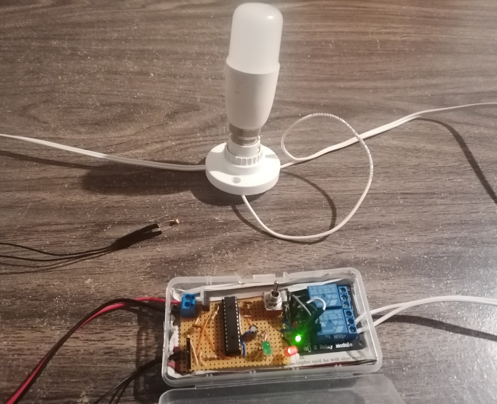
Automatic Night light Control using PIC32 Microcontroller
Date : 14 December 2024GIT Repository : view
Posted on : 17 Dec 2024
Tag(s) : PIC32, Automation, Mplab Harmony
In this project, we are designing and building a digital device that will automatically turn on the lights at night and turn them off during the day. Such a device offers convenience, energy savings, and improved automation at home.
Requirements
To accomplish this, we will need a light sensor and a circuit to process the sensor's signal. The circuit must also include a high-voltage switch to control the AC lamp. To ensure reliable operation:
- The circuit should activate only once during night-time and deactivate in the morning without errors.
- False positives must be avoided. The circuit must not turn on and off multiple times in a given day due to sudden changes in light conditions.
Approach
Light Sensor Selection
There are three potential light sensors we can use: photodiodes, phototransistors, or light-dependent resistors (LDRs). Each has their pros and cons:
- Photodiodes: These are more suitable for high-speed optical communications due to their fast response time and wavelength selectivity. They typically require an amplifier to boost the output current.
- Phototransistors: Produce an amplified current that is proportional to the light intensity, which makes them ideal for ambient light sensing.
- Light-Dependent Resistors (LDRs): On the other hand, are simpler and more cost-effective. They vary their resistance based on the light intensity but they respond much slower compared to photodiodes or phototransitors, this makes them ideal for avoiding false positives in this project.
Circuit Design
Several approaches can be used for circuit design, including an analog solution with comparator ICs or a microcontroller-based design. A microcontroller offers the simplest and most cost-effective solution. With that said, I think an analog approach might be an interesting challenge for future iterations. So be on the lookout for an analog version of this system in the future.
A relay module is used for high-voltage switching to control the AC lamp. This straightforward method ensures reliability. Also, we shall add a manual bypass switch for user control, this will allow the lamp to be operated independently without the circuit if needed.
Circuit Diagram
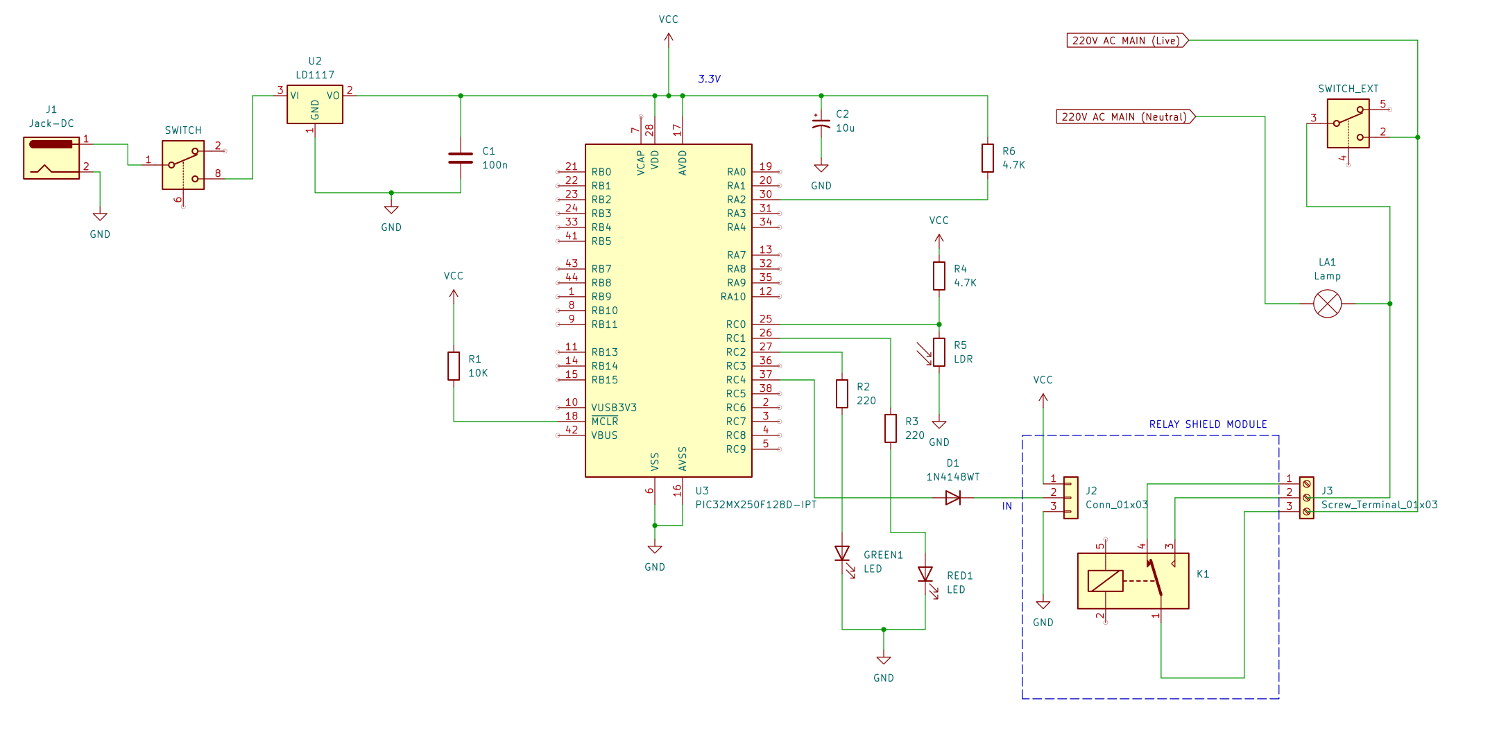
The microcontroller used is the PIC32MX250128B. The LDR forms a voltage divider with resistor R4, connected
to the ADC pin AN0 (RC0) of the microcontroller. The relay module used is a 3.3/5V relay board with active-low triggering,
ensuring a "fail-safe" operation if the microcontroller malfunctions.
A manual switch SWITCH_EXT is connected in parallel to the relay, enabling the user to bypass the system and control the lamp manually.
Software State Machine
The microcontroller was programmed using MPLAB Harmony. The system operates on a 31.25kHz internal oscillator for low power consumption. The finite state machine (FSM) managing the system is shown below.

The primary logic resides in the SERVICE_TASKS state, where ADC samples are polled, and an up/down counter is adjusted
based on light intensity. If the count exceeds 4 (approximately 2 minutes), the relay is triggered to switch the light.
The APP_STATE_ON_OVERRIDE is currently unreachable due to a pull-up resistor on pin RA2. This can be modified
if manual override via software is desired, although the parallel hardware switch already achieves this function.
Software Code
The complete software code is available on my GitHub repository. Note that the project uses the MPLAB Harmony framework, which must be installed to compile and run the code.
Conclusion
This project demonstrates a simple practical application of microcontroller-based automation. The design is straightforward, works well, and avoids unnecessary complexity. It’s a fun and practical project that shows how easy it can be to bring automation into everyday life.